Build a 24-Hour CMOS Clock Without Writing a Single Line of Code
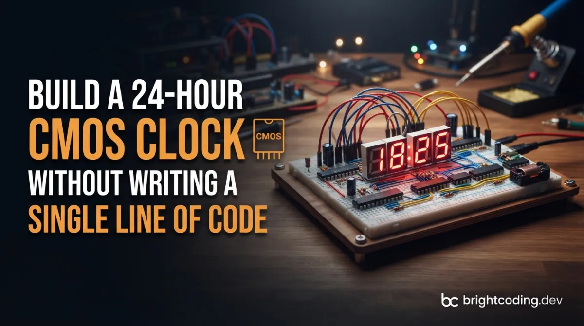
What if I told you that everything you believe about digital clocks is wrong?
For the past decade, we've been conditioned to think that every electronic gadget needs a brain—a microcontroller, firmware, lines of code, endless debugging sessions, and the sinking feeling when your Arduino sketch fails at 2 AM. But what if you could build something more reliable, more educational, and infinitely cooler without writing a single line of code? No setup() functions. No loop() headaches. No chasing down library dependencies that broke in version 3.2.1.
Enter the CMOS Digital Desk Clock by Dilshan—a jaw-dropping retro build that proves pure hardware logic still reigns supreme. This isn't nostalgia for nostalgia's sake. This is a fully functional 24-hour timepiece constructed entirely from classic 4000 series CMOS logic ICs, a 32.768kHz crystal, and the kind of point-to-point wiring craftsmanship that makes modern PCB designers weep with envy. No microcontrollers. No programmable logic. No firmware updates ever.
If you're a developer feeling burned out by software complexity, an electronics hobbyist craving tangible results, or simply someone who wants to understand how digital logic actually works at the gate level—this project will rewire your brain. The dilshan/cmos-clock repository isn't just a GitHub project. It's a masterclass in discrete digital design that every technologist should experience firsthand.
What Is the CMOS Digital Desk Clock?
The CMOS Digital Desk Clock is an open-hardware timepiece that displays hours, minutes, and seconds in 24-hour format using nothing but discrete CMOS logic components. Created by Dilshan and released under the Creative Commons Attribution 4.0 International license, this project stands as a deliberate rejection of the "throw a microcontroller at it" mentality that dominates modern maker culture.
At its heart lies a 32.768kHz quartz crystal—the same frequency found in wristwatches and real-time clock modules, chosen specifically because 32,768 equals 2^15, making binary division trivial. This precise oscillation is cascaded through CMOS divider ICs to generate a rock-solid 1 Hz "heartbeat" that drives the entire timekeeping engine. From there, BCD (Binary-Coded Decimal) counters increment each digit, BCD-to-seven-segment decoders translate those binary patterns into human-readable displays, and the whole symphony runs on a clean 5V regulated supply.
Why is this trending now? In an era of AI-generated code and black-box IoT devices, there's a growing movement among developers and hardware enthusiasts to understand technology at fundamental levels. The CMOS clock represents computational purity—every state change, every digit transition, every flicker of an LED is directly observable and explainable through Boolean logic. No hidden firmware blobs. No opaque compiler optimizations. Just electrons, gates, and the satisfying click of relays (well, almost).
The project also celebrates retro aesthetics deliberately. Housed in a handmade picture frame built from molded PVC bars, with components mounted on perfboard using point-to-point wiring, it's as much a piece of workshop art as functional electronics. That 200mA current draw? That's the warm glow of six seven-segment displays doing their job without any power-saving sleep modes—because this clock never sleeps, and it doesn't need to.
Key Features That Make This Build Extraordinary
Let's dissect what makes this CMOS clock special beyond the novelty of skipping microcontrollers entirely:
-
Fully Discrete CMOS Logic Design: Every function—timekeeping, counting, decoding, display driving—is implemented with individual 4000-series ICs. You'll find CD4060 oscillator/dividers, CD4020 or CD4040 ripple counters, CD4518 dual BCD counters, and CD4511 BCD-to-seven-segment latch/decoder/drivers working in concert. This isn't abstraction; it's architecture.
-
True 24-Hour Format: Unlike many simple clock kits that roll over at 12, this design properly counts 00:00:00 through 23:59:59. Achieving this requires additional logic for hours tens-digit limiting (it only needs 0-2) and rollover detection at 23:59:59→00:00:00—elegant problems with elegant hardware solutions.
-
Crystal-Controlled Precision: The 32.768kHz crystal provides ±20 ppm accuracy typically, meaning roughly ±1.7 seconds per day drift without calibration. Compare that to the software-dependent accuracy of microcontroller-based clocks where interrupt latency and loop timing introduce unpredictable jitter.
-
Hardware Time Setting Controls: Physical buttons increment hours, minutes, and seconds through debounced logic—no menu systems, no mode buttons with cryptic LED blinking patterns. The interface is immediate and transparent.
-
Six-Digit Seven-Segment LED Display: Hours (tens/units), minutes (tens/units), and seconds (tens/units) each get dedicated display positions with individual decoder drivers. The result is a bright, readable display that screams "I was built by someone who cares."
-
5V DC Single-Supply Operation: Simple power requirements mean USB power banks, wall adapters, or bench supplies all work. The 200mA consumption is modest for six LED displays and ~15 logic ICs actively switching.
Real-World Use Cases Where This Clock Shines
1. Electronics Education and Digital Logic Training
Universities still teach digital logic fundamentals, but students rarely build complete systems. This clock bridges theory and practice—every Karnaugh map simplification, every timing diagram, every propagation delay calculation has physical consequences you can measure with an oscilloscope. It's the capstone project that makes semesters of Boolean algebra click.
2. Workshop Bench Time Reference
Need a clock that always works? No SD card corruption, no WiFi dependency, no firmware bugs introduced by "improvements." This clock boots instantly, displays time continuously, and fails only with catastrophic hardware damage—which you can actually diagnose and repair with basic tools.
3. Retro Computing and Vintage Aesthetic Projects
Building a Z80 homebrew computer? A 6502 SBC? This clock fits the aesthetic perfectly. Its discrete logic design philosophy matches the era of classic computing, and the visible wiring becomes conversation-starting decor rather than something to hide in an enclosure.
4. Emergency Preparedness and EMP-Resistant Timekeeping
While your smart home devices become bricks after electromagnetic pulses, this clock's simplicity is its resilience. No flash memory to corrupt, no RF-sensitive receivers—just hardened CMOS logic that would survive conditions that fry more complex electronics.
5. Meditation on Technological Simplicity
Sometimes you need to remember that complexity is a choice. Building this clock forces you to confront how much we over-engineer solutions. The satisfaction of watching seconds tick by through pure hardware logic is oddly therapeutic in our notification-saturated world.
Step-by-Step Installation & Setup Guide
Ready to build? Here's your complete path from parts to ticking clock.
Phase 1: Procurement
First, download the complete Bill of Materials from the repository. You'll need:
| Category | Components |
|---|---|
| Timing | 32.768kHz crystal, CD4060 14-stage ripple counter/oscillator |
| Counters | CD4518 dual BCD counters (×3 for HH:MM:SS) |
| Decoders | CD4511 BCD-to-7-segment latch/decoder/drivers (×6) |
| Display | Common-cathode seven-segment LED displays (×6) |
| Logic | Additional gates for 24-hour rollover logic |
| Power | 5V regulator (7805), filtering capacitors |
| Misc | Resistors, capacitors, diodes, pushbuttons, perfboard, PVC frame materials |
Phase 2: Circuit Construction
Recommended build order (learn from my mistakes):
1. 5V power supply section — verify with multimeter first
2. Crystal oscillator + divider chain — confirm 1Hz output
3. Seconds counters and displays — get something visible quickly
4. Minutes counters with carry logic
5. Hours counters with 24-hour limiting logic
6. Time-setting button interfaces with debouncing
7. Final integration and enclosure mounting
The point-to-point wiring on perfboard demands patience. Use 30 AWG wire-wrap wire or magnet wire for clean, manageable connections. Color-code aggressively: red for VCC, black for GND, distinct colors for clock lines, data buses, and control signals.
Phase 3: Critical Adjustments
The 32.768kHz crystal may need load capacitance trimming for accuracy. Typical watch crystals want 12.5pF equivalent load—experiment with 10-22pF ceramic capacitors on the oscillator pins while monitoring against a GPS-disciplined reference or WWV time signal.
For the 1Hz output from the CD4060: the chip divides by 2^14 (16,384), so you'll need an additional ÷2 stage (flip-flop or additional counter stage) to reach exactly 1Hz from 32.768kHz. The repository details this division chain precisely.
REAL Code Examples: Understanding the Hardware Logic
Since this project has zero code, let's examine the schematic logic and construction patterns from the repository that function as the "source code" of this hardware project.
Example 1: The Crystal Oscillator and Divider Chain
This is the heartbeat of your clock—the equivalent of main() in a software project:
// Conceptual representation of the CD4060 oscillator configuration
// Pin connections for 32.768kHz crystal timebase

CD4060B oscillator_divider (
    .VDD(5V),
    .VSS(GND),
    // Crystal oscillator pins with load capacitors
    .OSCI(crystal_pin1),      // Series crystal + 22pF to GND
    .OSCO(crystal_pin2),      // 22pF to GND
    // Critical: CD4060 has internal oscillator amplifier
    // External crystal completes the feedback loop

    // Output stages (each divides by 2)
    .Q4(2048Hz),              // 32768 / 16 = 2048 Hz
    .Q5(1024Hz),              // 32768 / 32 = 1024 Hz
    .Q6(512Hz),               // Continue dividing...
    .Q7(256Hz),
    .Q8(128Hz),
    .Q9(64Hz),
    .Q10(32Hz),
    .Q11(16Hz),
    .Q12(8Hz),
    .Q13(4Hz),                // 32768 / 8192 = 4 Hz
    .Q14(2Hz)                 // 32768 / 16384 = 2 Hz
    // Note: Missing Q1-Q3 and Q15 on this package
);

// External ÷2 stage needed: 2Hz → 1Hz
// Use CD4013 dual D-flip-flop or CD4027 JK-flip-flop
CD4013 final_divider (
    .CLK(Q14_from_4060),      // 2Hz input
    .D(Q_bar),                // Toggle mode: D = !Q
    .Q(1Hz_output),           // Precise 1 second pulses
    .Q_bar(feedback_to_D)     // Completes toggle connection
);
What's happening here? The CD4060 combines a crystal oscillator amplifier with a 14-stage binary ripple counter. The crystal's mechanical resonance creates electrical oscillation, amplified by internal inverters, with the 22pF capacitors setting the exact frequency. Each Q output divides by an additional power of two. Since 32,768 = 2^15 and the CD4060 provides ÷2^14 maximum, we need one more flip-flop stage to reach the magical 1Hz that drives our seconds counter.
Example 2: BCD Counter Cascading for Time Digits
// Seconds units: counts 0-9, then resets and carries
CD4518 seconds_units (
    .CLOCK(1Hz_from_divider),
    .RESET(clear_at_10),      // Active when count reaches 10
    .ENABLE(1'b1),            // Always enabled
    .CARRY_OUT(tc_output),    // Terminal count at '1001' (9)
    .Q0-Q3(BCD_seconds_units) // 4-bit BCD output to decoder
);

// Detect '10' (1010 binary) for reset
assign clear_at_10 = (Q3 & !Q2 & Q1 & !Q0); // 1010 = decimal 10

// Seconds tens: counts 0-5, enabled by units carry
CD4518 seconds_tens (
    .CLOCK(1Hz_from_divider), // Same clock, but...
    .ENABLE(tc_from_units),   // Only counts when units rolls over
    .RESET(clear_at_6),       // Reset at '0110' (6)
    .CARRY_OUT(minutes_enable),
    .Q0-Q3(BCD_seconds_tens)
);

// Detect '6' (0110) for reset
assign clear_at_6 = (!Q3 & Q2 & Q1 & !Q0); // 0110 = decimal 6
The elegance here: Each digit is a independent BCD counter, but they're synchronized through carry chains. The units digit runs freely on 1Hz. When it transitions from 9→0, its terminal count output briefly pulses, enabling the tens digit to increment. The tens digit self-resets at 6, not 10, because 60 seconds = 1 minute. This pattern repeats for minutes, with hours requiring additional logic for the 24-hour limit.
Example 3: Seven-Segment Display Driving
// CD4511: BCD in, segment drive out
// Active HIGH outputs for common-cathode displays

CD4511 segment_decoder (
    .A(BCD_bit0),             // Least significant BCD bit
    .B(BCD_bit1),
    .C(BCD_bit2),
    .D(BCD_bit3),             // Most significant BCD bit
    .LT(1'b1),                // Lamp Test: normal operation
    .BI(1'b1),                // Blanking Input: display enabled
    .LE(1'b0),                // Latch Enable: transparent mode

    // Segment outputs (a-g) with current-limiting resistors
    .a(segment_a),            // 220Ω to 330Ω resistor each
    .b(segment_b),
    .c(segment_c),
    .d(segment_d),
    .e(segment_e),
    .f(segment_f),
    .g(segment_g)
    // Standard 7-segment patterns: 0=abcdef, 1=bc, 2=abged, etc.
);

// Physical connection to common-cathode display
// All cathodes tied to GND through transistor or directly
// Anodes driven through resistors from CD4511 outputs
Critical insight: The CD4511 includes internal latch functionality (LE pin) and blanking control. For a clock that updates continuously, we keep LE low for transparent mode. The 220-330Ω resistors aren't optional—they limit segment current to ~10-15mA, keeping total display current manageable and preventing LED burnout.
Advanced Usage & Best Practices
Accuracy Enhancement: For obsessive precision, add a temperature-compensated crystal oscillator (TCXO) module or discipline the clock against mains frequency (50/60Hz) where power grid stability provides long-term accuracy. Alternatively, implement a manual trimmer capacitor in the oscillator circuit for fine frequency adjustment—mark your "fast" and "slow" calibration points.
Power Supply Purity: CMOS logic is surprisingly tolerant, but clock jitter from power supply noise directly impacts timekeeping. Use 10µF electrolytic + 100nF ceramic decoupling at every IC power pin. A linear regulator (not switching) eliminates high-frequency noise that could couple into the oscillator.
Display Multiplexing vs. Static: This design uses static drive (each digit continuously lit) rather than multiplexing. While multiplexing reduces component count, it introduces visible flicker, requires faster switching logic, and complicates the already-interesting timing. Static drive's higher component count is a fair trade for simplicity and brightness.
Enclosure Thermal Management: Those six LED displays at 200mA generate noticeable warmth. Ensure your PVC frame enclosure has ventilation slots—not just for component longevity, but because heat affects crystal frequency. A 10°C rise can shift frequency by 10-20 ppm, accumulating to minutes per month error.
Documentation Discipline: As you build, photograph each stage before adding the next layer of wiring. Point-to-point builds become impenetrable mazes quickly. Dilshan's approach of methodical construction documentation in the repository sets the standard—follow it.
Comparison with Alternatives
| Feature | CMOS Clock (dilshan/cmos-clock) | Arduino/Raspberry Pi Clock | GPS-Synchronized Clock | Commercial Atomic Clock |
|---|---|---|---|---|
| Microcontroller Required | ❌ None | ✅ Required | ✅ Required | ✅ Complex system |
| Firmware/Code | ❌ Zero lines | ✅ Dozens to hundreds | ✅ Hundreds+ | ✅ Proprietary |
| Understanding Level | Gate-level deep | Library abstraction | Module abstraction | Black box |
| Build Time | 8-20 hours | 2-4 hours | 3-6 hours | Purchased complete |
| Accuracy | ±20 ppm (trimmed) | Dependent on resonator | ±0.01 ppm | ±0.0001 ppm |
| Power Consumption | ~200mA | 50-500mA | 100-300mA | Wall-powered |
| Educational Value | ⭐⭐⭐⭐⭐ Maximum | ⭐⭐⭐ Moderate | ⭐⭐⭐ Moderate | ⭐ Minimal |
| Aesthetic Appeal | ⭐⭐⭐⭐⭐ Handmade art | ⭐⭐ Functional | ⭐⭐⭐ Clean | ⭐⭐⭐ Professional |
| Repairability | ⭐⭐⭐⭐⭐ Component-level | ⭐⭐⭐ Module swap | ⭐⭐⭐ Module swap | ⭐ Service only |
| Cost (components) | $15-30 | $10-25 | $25-50 | $50-5000 |
The verdict? Choose the CMOS clock when learning, understanding, and craftsmanship matter more than convenience. Choose microcontroller solutions when you need features (WiFi sync, alarms, temperature display) or rapid prototyping. Choose GPS/atomic when absolute precision is non-negotiable. But only the CMOS build gives you that irreplaceable I built this from logic gates satisfaction.
Frequently Asked Questions
Q: Can I modify this for 12-hour format with AM/PM indicator? A: Absolutely! Add a flip-flop toggled at 12:00:00, and modify the hours tens/units reset logic to roll 12→01 instead of 23→00. An additional LED or segment indicates AM/PM state. The repository's discrete logic approach makes such modifications transparent.
Q: How accurate is this compared to my phone's clock? A: Untrimmed: potentially ±2 minutes/month. With careful crystal load capacitance tuning against a reference: ±10 seconds/month. For better long-term accuracy, add a DS3231 TCXO module as external timebase, though this slightly compromises the "pure CMOS" philosophy.
Q: Can I use common-anode displays instead? A: Yes, but you'll need CD4513 (active-low outputs) or add inverter stages. The CD4511 is designed for common-cathode. Verify your display type before ordering—mixing them up means desoldering dozens of connections.
Q: Is this project suitable for beginners? A: It's intermediate-level. You need soldering proficiency, basic understanding of binary/hex/BCD, and patience for debugging invisible logic states. However, it's arguably more educational than microcontroller projects because every signal is probe-able and every function maps directly to a physical component.
Q: What tools are essential for troubleshooting? A: Digital multimeter for DC levels, oscilloscope for clock signals (even a cheap 10MHz USB scope works), logic probe for quick high/low/pulse detection, and bright desk lamp for inspecting hair-wire solder joints. A second person to read schematics while you probe helps immensely.
Q: Can I add battery backup for power failures? A: Yes! The CMOS 4000 series operates down to 3V. Add a 3V lithium coin cell with diode OR-ing to maintain oscillator and counters during outages. Display can extinguish to save power—timekeeping continues invisible until mains returns.
Q: Where can I find the complete schematics and PCB layouts? A: All design files, detailed schematics, and the complete bill of materials are available in the dilshan/cmos-clock GitHub repository. The project is released under CC BY 4.0, so you're free to adapt, improve, and share your builds with proper attribution.
Conclusion: Rediscover the Joy of Pure Hardware
In a world where we increasingly interact with technology through layers of abstraction—frameworks on frameworks, containers in clouds, models generating code—there's profound satisfaction in building something where cause and effect are immediate and visible. The CMOS Digital Desk Clock isn't anti-technology; it's pro-understanding. Every LED segment that illuminates traces directly to a specific transistor switching in a specific IC at a specific moment, following rules you can hold in your head entirely.
Dilshan's creation reminds us that the "old ways" weren't primitive—they were foundational. The same CMOS logic families in this clock underpin the billions of transistors in your smartphone's processor. Understanding them at human scale makes the modern miracle less mysterious and more marvelous.
Whether you're a software developer seeking hardware literacy, an educator designing curriculum, or a maker craving a project with soul, this clock delivers. The 20 hours you'll spend hunched over perfboard, cursing slipped wires and celebrating first successful digit counts, will reshape how you think about digital systems.
Stop letting microcontrollers think for you. Build a clock that thinks in gates.
👉 Start your build today: Visit the dilshan/cmos-clock repository, download the bill of materials, and join the growing community of developers rediscovering that the best code is sometimes no code at all. Share your build photos, fork the design, improve the accuracy, make it yours—and don't forget to star the repo to show appreciation for open hardware craftsmanship at its finest.
Tick. Tock. The future is retro.
Tags
Explore on the BrightCoding network
Hand-picked resources from our other sites.
Hacker Fab: Build Your Own Semiconductor Lab for Under $50K
Hacker Fab is revolutionizing semiconductor manufacturing with open-source documentation to build complete nanofabrication labs for under $50K. Learn how to joi...
The Ultimate Raspberry Pi Resource Bible: 15,000+ Stars, 100+ Tools, and Endless Project Possibilities
The Raspberry Pi has revolutionized the world of computing since its introduction in 2012, transforming from a simple educational tool into a versatile platfor...
lraton/FlopperZiro: A DIY Flipper Zero Clone for Arduino Builders
lraton/FlopperZiro is an open-source, Arduino-based DIY clone of the Flipper Zero multi-tool. Built around the STM32-L432KC, it supports BadUSB, RFID/NFC, IR, a...
Continuez votre lecture

$96 DIY Guided Rocket: The MANPADS Prototype Exposed

This $15 Linux Board Makes Raspberry Pi Look Overpriced

Stop Buying Expensive Counters! ESP32-Paxcounter Does It for $10

Stop Coding Alone: OPC-Skills Gives Your AI Agent Superpowers
Commentaires 0
Aucun commentaire pour l'instant. Soyez le premier à réagir !