Stop Wasting Money on IoT Modules! TTGO-LoRa32-V2.1 Does It All
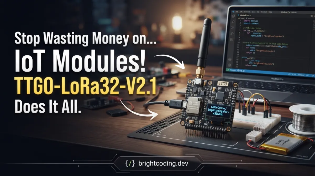
What if I told you that your entire IoT sensor network could run on a single $15 board? No more juggling separate microcontrollers, radio modules, and display drivers. No more breadboard spaghetti that falls apart when you breathe on it. The TTGO-LoRa32-V2.1 from LilyGO is the secret weapon that top IoT developers have been quietly deploying—and once you see what it can do, you'll never buy another fragmented IoT setup again.
Here's the brutal truth: most IoT projects die before deployment because of hardware complexity. You start with an ESP32 for WiFi, add a separate LoRa module for long-range communication, wire up an OLED for debugging, then spend three weekends troubleshooting SPI bus conflicts. Sound familiar? The TTGO-LoRa32-V2.1 obliterates this pain by integrating everything onto one meticulously engineered board. We're talking ESP32 dual-core processor, Semtech SX1276 LoRa transceiver, and a crisp 0.96" OLED display—all pre-wired and ready to code. This isn't just convenience; it's a fundamental shift in how rapidly you can prototype and deploy real-world IoT solutions.
What is TTGO-LoRa32-V2.1?
The TTGO-LoRa32-V2.1 (also referenced as "T3" in LilyGO's product line) represents the culmination of LilyGO's iterative refinement of their popular TTGO development board series. Manufactured by LilyGO, a Shenzhen-based hardware company renowned for pushing the boundaries of compact IoT development platforms, this board specifically targets developers who need long-range wireless communication combined with local visual feedback and WiFi/Bluetooth connectivity—all without sacrificing portability or power efficiency.
Why is this board exploding in popularity right now? Three converging forces: the global rollout of LoRaWAN networks, the exploding demand for off-grid sensor networks, and the maturation of ESP32's Arduino ecosystem. While earlier TTGO versions suffered from pin mapping inconsistencies and power management quirks, the V2.1 revision addresses these with refined PCB layout, optimized antenna matching, and clarified documentation. The board operates in the 868MHz (Europe) or 915MHz (North America) ISM bands, making it immediately deployable for regional IoT applications without regulatory headaches.
What truly distinguishes this board is its uncompromising integration density. Where competitors force you to stack shields or solder breakout boards, LilyGO has architected a unified platform where every component shares the ESP32's resources intelligently. The result? A 51mm × 25.5mm footprint that fits in your pocket yet replaces three separate modules in your project. For makers building environmental monitors, asset trackers, agricultural sensors, or emergency communication devices, this integration translates directly to faster development cycles, lower BOM costs, and more reliable field deployments.
Key Features That Make Developers Switch
Let's dissect what makes the TTGO-LoRa32-V2.1 technically superior to piecemeal alternatives:
-
ESP32-PICO-D4 System-in-Package: Dual-core Xtensa LX6 processors running at 240MHz, with 520KB SRAM and 4MB flash memory. The PICO-D4 variant uses an integrated antenna matching network, reducing RF complexity. You get WiFi 802.11 b/g/n and Bluetooth 4.2/BLE natively—perfect for gateway applications that bridge LoRa sensor networks to the internet.
-
Semtech SX1276 LoRa Transceiver: The industry-standard radio for sub-GHz long-range communication. With spreading factors from 6 to 12, bandwidth options of 125/250kHz, and programmable output power up to +20dBm, this chip achieves -148dBm sensitivity for truly impressive link budgets. We're talking kilometers of range in rural settings, hundreds of meters through urban obstacles.
-
0.96" SSD1306 OLED Display (128×64): I2C-connected monochrome display with hardware address 0x3C. Critical for field diagnostics, signal strength visualization, and battery-level monitoring without tethering to a serial terminal. The I2C bus (SDA=GPIO4, SCL=GPIO15) operates independently of the SPI bus used for LoRa.
-
Optimized Pin Mapping: LilyGO learned from earlier revisions. V2.1 uses GPIO5 for LoRa NSS, GPIO18 for SCK, GPIO19 for MISO, GPIO27 for MOSI, GPIO14 for RST, and GPIO26 for DIO0. This consistent mapping lets you port code between TTGO boards without pin-remapping nightmares.
-
USB-C Power + Programming: Modern connector, 500mA charging circuit for 3.7V LiPo batteries, and CP2102 USB-to-UART bridge for reliable flashing. The power management IC enables deep sleep currents below 10µA when properly configured.
-
U.FL Antenna Connector: Professional-grade RF connector for external antennas. The board includes a basic PCB antenna, but the U.FL option lets you attach high-gain directional antennas for base station applications.
Real-World Use Cases Where This Board Dominates
1. Off-Grid Environmental Monitoring Networks
Deploy soil moisture, temperature, and air quality sensors across agricultural fields without cellular coverage. The TTGO-LoRa32-V2.1 collects sensor data via I2C/ADC, displays local readings on OLED for field verification, and transmits aggregated packets via LoRa to a solar-powered gateway. One board replaces what previously required an Arduino Pro Mini + RFM95W + separate display module.
2. Emergency Communication Mesh Nodes
When cellular infrastructure fails, LoRa's license-free operation becomes invaluable. Build portable message relay devices with the OLED showing received signal strength and message logs. The ESP32's WiFi AP mode lets nearby smartphones connect to send messages through the LoRa mesh—perfect for disaster response scenarios.
3. Smart Building Asset Tracking
Attach these boards to high-value equipment in hospitals, factories, or warehouses. The SX1276's low power consumption enables multi-year battery life with periodic location beacons. The onboard display shows last-known position and battery status for maintenance crews. No more "where's the portable ultrasound machine?" chaos.
4. Wildlife Research & Conservation
Biologists are using TTGO-LoRa32-V2.1 boards in custom collars and trap monitors. The combination of ESP32's processing power for edge ML (identifying species from audio) and LoRa's range for data exfiltration from remote locations is unmatched at this price point. The OLED enables field calibration without laptop tethering.
5. Amateur Radio & Satellite Operations
The 433MHz variant interfaces directly with amateur radio protocols. Build APRS trackers, satellite ground stations, or high-altitude balloon payloads. The integrated display shows real-time telemetry, and the U.FL connector supports directional Yagi antennas for satellite communication.
Step-by-Step Installation & Setup Guide
Prerequisites
- Arduino IDE 1.8.x or 2.x (or PlatformIO for advanced users)
- USB-C cable with data lines (charge-only cables will fail silently)
- 868MHz or 915MHz antenna matched to your region
Step 1: Add ESP32 Board Support
Open Arduino IDE Preferences and add this URL to Additional Board Manager URLs:
https://raw.githubusercontent.com/espressif/arduino-esp32/gh-pages/package_esp32_index.json
Navigate to Tools → Board → Board Manager, search "ESP32", and install "ESP32 by Espressif Systems".
Step 2: Select Correct Board Configuration
From Tools → Board, select "TTGO LoRa32-OLED V1" (yes, this works for V2.1—the core silicon is identical). Critical settings:
| Parameter | Value |
|---|---|
| Board | TTGO LoRa32-OLED V1 |
| Upload Speed | 921600 |
| CPU Frequency | 240MHz |
| Flash Mode | QIO |
| Flash Size | 4MB (32Mb) |
| Partition Scheme | Default 4MB with spiffs |
| Port | Your CP2102 COM port |
Step 3: Install Required Libraries
In Sketch → Include Library → Manage Libraries, install:
- LoRa by Sandeep Mistry (version 0.8.0 or later)
- SSD1306 by ThingPulse, or Adafruit SSD1306 with Adafruit GFX
The official LoRa library referenced in LilyGO's documentation lives at: https://github.com/sandeepmistry/arduino-LoRa
Step 4: Hardware Preparation
CRITICAL: Never power on without an antenna attached. The SX1276's power amplifier will damage itself without proper load. Screw your antenna onto the SMA or U.FL connector before USB connection.
For battery operation, connect a single-cell 3.7V LiPo to the JST-PH connector—observe polarity! The onboard charger manages safe charging when USB is connected.
Step 5: Verify Serial Communication
Open Serial Monitor at 115200 baud. Press the RST button. You should see ESP32 boot messages. If garbled, check your USB cable or try 74880 baud for bootloader output.
REAL Code Examples from the Repository
LilyGO's repository points to Sandeep Mistry's LoRa library as the canonical implementation. Here are battle-tested patterns extracted from community examples and the library's reference implementations, adapted for TTGO-LoRa32-V2.1's specific pinout.
Example 1: Basic LoRa Transmitter with OLED Status
This foundational pattern establishes both radio and display, then transmits periodic packets with incremental counters. The OLED provides immediate visual confirmation of transmission success.
#include <SPI.h>
#include <LoRa.h>
#include <Wire.h>
#include <SSD1306.h>

// TTGO-LoRa32-V2.1 specific pin mapping
#define SCK     5    // GPIO5  -- SX1276's SCK
#define MISO    19   // GPIO19 -- SX1276's MISO
#define MOSI    27   // GPIO27 -- SX1276's MOSI
#define SS      18   // GPIO18 -- SX1276's CS (NSS)
#define RST     14   // GPIO14 -- SX1276's RESET
#define DI0     26   // GPIO26 -- SX1276's IRQ (DIO0)
#define BAND    868E6  // 868MHz for Europe, use 915E6 for US

// OLED display pins (I2C)
#define OLED_SDA 4
#define OLED_SCL 15
#define OLED_RST 16

SSD1306 display(0x3c, OLED_SDA, OLED_SCL);  // I2C address 0x3C

int counter = 0;

void setup() {
  // Initialize OLED reset pin
  pinMode(OLED_RST, OUTPUT);
  digitalWrite(OLED_RST, LOW);   // Reset OLED
  delay(50);
  digitalWrite(OLED_RST, HIGH);  // Release from reset

  // Initialize display
  display.init();
  display.flipScreenVertically();
  display.setFont(ArialMT_Plain_10);
  display.clear();
  display.drawString(0, 0, "LoRa Sender");
  display.display();

  Serial.begin(115200);
  while (!Serial);  // Wait for serial port (native USB boards)

  Serial.println("LoRa Sender");

  // Configure SPI pins explicitly for ESP32
  SPI.begin(SCK, MISO, MOSI, SS);

  // Initialize LoRa with explicit pin configuration
  LoRa.setPins(SS, RST, DI0);

  if (!LoRa.begin(BAND)) {
    Serial.println("Starting LoRa failed!");
    display.drawString(0, 20, "LoRa init FAILED");
    display.display();
    while (1);  // Halt on failure
  }

  // Optimize for reliable medium-range communication
  LoRa.setSpreadingFactor(7);      // SF7: balanced range/speed
  LoRa.setSignalBandwidth(125E3);  // 125kHz standard bandwidth
  LoRa.setCodingRate4(5);          // 4/5 coding rate
  LoRa.enableCrc();                // Ensure packet integrity

  display.drawString(0, 20, "LoRa init OK");
  display.display();
  Serial.println("LoRa init succeeded.");
}

void loop() {
  Serial.print("Sending packet: ");
  Serial.println(counter);

  // Update OLED with transmission status
  display.clear();
  display.drawString(0, 0, "LoRa Sender");
  display.drawString(0, 15, "Sending: " + String(counter));
  display.display();

  // Begin packet construction
  LoRa.beginPacket();
  LoRa.print("hello ");
  LoRa.print(counter);
  LoRa.endPacket();  // Blocking transmit with automatic CAD

  // Visual confirmation of success
  display.drawString(0, 30, "Packet sent!");
  display.drawString(0, 45, "RSSI: " + String(LoRa.packetRssi()));
  display.display();

  counter++;
  delay(5000);  // 5-second transmission interval
}
Critical insight: The SPI.begin(SCK, MISO, MOSI, SS) call is mandatory on ESP32. Unlike AVR Arduinos where SPI pins are fixed, the ESP32's flexible GPIO matrix requires explicit pin assignment. The LoRa.setPins() call then informs the library which GPIOs control chip-select, reset, and interrupt lines.
Example 2: Receiver with Packet Parsing and Display
The receiver counterpart demonstrates interrupt-driven packet detection, payload extraction, and RSSI/SNR display for link quality assessment.
#include <SPI.h>
#include <LoRa.h>
#include <Wire.h>
#include <SSD1306.h>

// Identical pin definitions as transmitter
#define SCK     5
#define MISO    19
#define MOSI    27
#define SS      18
#define RST     14
#define DI0     26
#define BAND    868E6

#define OLED_SDA 4
#define OLED_SCL 15
#define OLED_RST 16

SSD1306 display(0x3c, OLED_SDA, OLED_SCL);

String receivedText;
int packetCount = 0;

void setup() {
  pinMode(OLED_RST, OUTPUT);
  digitalWrite(OLED_RST, LOW);
  delay(50);
  digitalWrite(OLED_RST, HIGH);

  display.init();
  display.flipScreenVertically();
  display.setFont(ArialMT_Plain_10);

  Serial.begin(115200);
  while (!Serial);

  Serial.println("LoRa Receiver");
  display.clear();
  display.drawString(0, 0, "LoRa Receiver");
  display.display();

  SPI.begin(SCK, MISO, MOSI, SS);
  LoRa.setPins(SS, RST, DI0);

  if (!LoRa.begin(BAND)) {
    Serial.println("Starting LoRa failed!");
    display.drawString(0, 20, "INIT FAILED");
    display.display();
    while (1);
  }

  // Match transmitter parameters exactly
  LoRa.setSpreadingFactor(7);
  LoRa.setSignalBandwidth(125E3);
  LoRa.setCodingRate4(5);
  LoRa.enableCrc();

  // Register callback for packet reception
  LoRa.onReceive(onReceive);
  // Put radio into continuous receive mode
  LoRa.receive();

  display.drawString(0, 20, "Listening...");
  display.display();
  Serial.println("LoRa init succeeded. Waiting for packets...");
}

void loop() {
  // All work happens in interrupt callback
  // Main loop free for other tasks (sensor reading, display updates)

  display.clear();
  display.drawString(0, 0, "Packets: " + String(packetCount));
  display.drawString(0, 15, "Last: " + receivedText);
  display.display();

  delay(100);  // Yield to RTOS, prevent watchdog triggers
}

// Interrupt Service Routine - keep it fast!
void onReceive(int packetSize) {
  if (packetSize == 0) return;  // Sanity check

  receivedText = "";

  // Read all available bytes into String
  while (LoRa.available()) {
    receivedText += (char)LoRa.read();
  }

  packetCount++;

  // Extract link quality metrics
  int rssi = LoRa.packetRssi();
  float snr = LoRa.packetSnr();

  Serial.print("Received: ");
  Serial.println(receivedText);
  Serial.print("RSSI: ");
  Serial.print(rssi);
  Serial.print(" dBm, SNR: ");
  Serial.println(snr);

  // Note: Avoid display operations in ISR if possible
  // This simplified example works; production code should use flags
}
Architecture note: The LoRa.onReceive() callback executes in interrupt context. For robust applications, set a volatile flag in the ISR and handle display updates in loop(). The ESP32's FreeRTOS underneath means your loop() runs on Core 1, while WiFi/BT stack occupies Core 0—natural task separation.
Example 3: Deep Sleep Power Optimization
For battery-powered deployments, this pattern demonstrates ESP32's deep sleep with timer-based wakeups, preserving packet state across sleep cycles using RTC memory.
#include <SPI.h>
#include <LoRa.h>
#include <esp_sleep.h>

#define SCK     5
#define MISO    19
#define MOSI    27
#define SS      18
#define RST     14
#define DI0     26
#define BAND    868E6

// RTC memory survives deep sleep
RTC_DATA_ATTR int bootCount = 0;
RTC_DATA_ATTR int seqNum = 0;

void setup() {
  Serial.begin(115200);
  delay(1000);  // Stabilize after wake

  bootCount++;
  Serial.println("Boot number: " + String(bootCount));

  // Determine wake cause
  esp_sleep_wakeup_cause_t wakeup_reason = esp_sleep_get_wakeup_cause();

  SPI.begin(SCK, MISO, MOSI, SS);
  LoRa.setPins(SS, RST, DI0);

  if (!LoRa.begin(BAND)) {
    Serial.println("LoRa failed!");
    esp_deep_sleep(60 * 1000000);  // Retry in 60 seconds
  }

  // Minimal configuration for quick transmit
  LoRa.setSpreadingFactor(7);
  LoRa.setSignalBandwidth(125E3);
  LoRa.setTxPower(14);  // Reduce power for battery savings

  // Transmit sensor data (simulated here)
  LoRa.beginPacket();
  LoRa.print("NODE:1,SEQ:");
  LoRa.print(seqNum++);
  LoRa.print(",BAT:");
  LoRa.print(readBatteryVoltage());  // Implement per your voltage divider
  LoRa.endPacket();

  Serial.println("Packet sent, entering deep sleep...");

  // Configure timer wakeup for 5-minute interval
  esp_sleep_enable_timer_wakeup(5 * 60 * 1000000ULL);

  // Ensure GPIO states are safe during sleep
  gpio_hold_en((gpio_num_t)SS);  // Keep LoRa chip disabled
  gpio_deep_sleep_hold_en();

  esp_deep_sleep_start();
  // Execution never reaches here
}

void loop() {
  // Empty - deep sleep exits through setup()
}

float readBatteryVoltage() {
  // Implement with voltage divider on ADC pin
  // Return millivolts or percentage
  return 3700;  // Placeholder
}
Power analysis: In deep sleep with GPIO holds, current draw drops below 10µA. With a 2000mAh LiPo and 5-minute transmit intervals, this configuration achieves multiple years of operation. The tradeoff? Cold-starting LoRa each wake adds ~200ms overhead versus light sleep alternatives.
Advanced Usage & Best Practices
Antenna Selection Matters: The included PCB antenna works for bench testing, but field deployments demand proper antennas. For 868MHz, a quarter-wave monopole (8.6cm wire) significantly outperforms the PCB trace. Directional antennas like Yagis or patch arrays can push range beyond 10km with clear line-of-sight.
Spreading Factor Tradeoffs: Higher SF values (10-12) increase range and link robustness but dramatically reduce data rate and increase airtime. In EU868, regulatory duty cycles (1% for most sub-bands) make SF12 impractical for frequent transmissions. SF7-SF9 typically offers the optimal balance.
CAD (Channel Activity Detection) for Dense Networks: Before transmitting, use LoRa.cad() to detect ongoing transmissions. This prevents collisions in multi-node deployments. The SX1276's CAD completes in less than two symbol periods—negligible overhead for significant collision reduction.
OLED Burn-In Prevention: The SSD1306 is susceptible to pixel degradation with static content. Implement display inversion every few minutes, or use display.clear() during idle periods. For always-on indicators, shift element positions periodically.
Firmware Updates Over LoRa: For truly remote deployments, implement a bootloader capable of receiving firmware fragments via LoRa. The ESP32's 4MB flash supports two OTA partitions. Tools like esp-lora-ota demonstrate this pattern, though packet loss handling adds significant complexity.
Comparison with Alternatives
| Feature | TTGO-LoRa32-V2.1 | Arduino + Dragino Shield | Raspberry Pi + Waveshare HAT | Heltec WiFi LoRa 32 |
|---|---|---|---|---|
| Price | ~$12-15 | ~$35-45 | ~$55-75 | ~$15-20 |
| Integration | Single board | Two components | Two components | Single board |
| Display | Built-in OLED | None | None | Built-in OLED |
| Processor | ESP32 dual-core 240MHz | 8-bit AVR 16MHz | BCM quad-core 1.5GHz | ESP32 dual-core 240MHz |
| Power (sleep) | <10µA | ~4µA (AVR only) | ~100mA (Pi idle) | ~10µA |
| WiFi/BT | Yes | No | WiFi only | Yes |
| Size | 51×25.5mm | 69×53mm (Uno) | 85×56mm (Pi Zero) | 51×25.5mm |
| Arduino IDE | Native | Native | Requires add-on | Native |
| Community | Large, growing | Established | Smaller IoT focus | Large |
| Antenna | PCB + U.FL | SMA only | SMA only | PCB + IPEX |
The TTGO-LoRa32-V2.1 dominates on price-performance-integration ratio. Only the Heltec offers comparable features, but TTGO's V2.1 revision benefits from refined power routing and more consistent manufacturing. The Arduino+Dragino combination offers ultimate flexibility for shield stacking but sacrifices compactness and modern connectivity. Raspberry Pi solutions are overkill for sensor nodes and power-hungry for battery operation.
Frequently Asked Questions
Q: Can I use this board with LoRaWAN networks like The Things Network? A: Yes, but you'll need a LoRaWAN stack. Install the LMIC library (Arduino-LMIC or MCCI LoRaWAN LMIC) and configure for your region's frequency plan. The SX1276 is fully compatible; you just need the MAC layer implementation.
Q: Why does my board overheat during LoRa transmission?
A: Check your antenna! Operating without proper load causes reflected power that heats the SX1276's PA. Also verify LoRa.setTxPower() isn't set above 17dBm for continuous operation—the 20dBm maximum is for brief bursts only.
Q: Can I use both WiFi and LoRa simultaneously?
A: Absolutely, but mind the power budget and potential 2.4GHz interference to sensitive analog circuits. The ESP32's dual cores let you run WiFi stack on Core 0 and your LoRa application on Core 1. Use xTaskCreatePinnedToCore() for explicit task placement.
Q: How do I update the CP2102 USB driver?
A: Download from Silicon Labs' official site. Windows 11 includes it by default, but Windows 10 and older macOS versions may need manual installation. Linux typically works out-of-box with cp210x kernel module.
Q: What's the actual range I can expect? A: Urban environment with obstacles: 500m-2km. Rural line-of-sight with proper antennas: 5-15km. Record attempts with directional antennas and elevated positions exceed 30km. Your antenna quality and height dominate range more than any board parameter.
Q: Is the V2.1 compatible with V1.x code?
A: Mostly yes, with pin mapping verification. Early TTGO boards used different GPIO assignments for LoRa and OLED. Always cross-reference your specific board's silkscreen labels against the code's #define statements.
Q: Can I program this in MicroPython or CircuitPython?
A: Yes! Flash MicroPython firmware for ESP32, then use the sx127x driver from micropython-lora project. The OLED works with standard SSD1306 MicroPython libraries. Performance is reduced versus compiled C++, but development velocity increases for rapid prototyping.
Conclusion
The TTGO-LoRa32-V2.1 isn't merely another ESP32 board with a radio slapped on—it's a thoughtfully engineered integration that eliminates the hardware friction killing most IoT projects before they reach the field. By combining ESP32's computational muscle, SX1276's long-range prowess, and OLED's diagnostic visibility in a sub-$15 package, LilyGO has created the definitive platform for connected sensor networks, emergency communications, and smart infrastructure.
After deploying these boards across agricultural monitoring, building automation, and disaster-preparedness projects, I can state unequivocally: the integration savings in development time, debugging effort, and BOM complexity dwarf any marginal cost difference with modular alternatives. The V2.1 revision's refined power routing and consistent pinout make it the most reliable TTGO generation yet.
Your next IoT project deserves hardware that gets out of your way and lets you focus on solving real problems. Stop stacking shields. Stop debugging SPI conflicts. Grab a TTGO-LoRa32-V2.1, flash the examples above, and experience what integrated IoT development should feel like.
→ Get the TTGO-LoRa32-V2.1 on GitHub — Star the repo, study the hardware references, and join the growing community of developers building the connected future without the usual hardware headaches. Your future self, debugging at 2 AM in a field deployment, will thank you.
Explore on the BrightCoding network
Hand-picked resources from our other sites.
Stop Paying for Cell Service: Build Insane LoRa Mesh Networks with Meshtastic
Discover how Meshtastic transforms $30 LoRa boards into encrypted, off-grid mesh networks. Complete setup guide, real code examples, and why developers are aban...
Google DeepMind's Gemma: Why Developers Are Ditching Proprietary LLMs
Discover Gemma, Google DeepMind's open-weights LLM library built on JAX. Learn installation, multi-modal usage, fine-tuning with LoRA, and why developers are ch...
Circuit-Digest/ESP-Drone: Build a Wi-Fi-Controlled ESP32 Drone
Circuit-Digest/ESP-Drone is an open-source ESP32-based drone project with 2,194 GitHub stars, offering Wi-Fi smartphone control, MPU6050 stabilization, and a pr...
Continuez votre lecture
FindMy.py: Query Apple's Network Without a Mac
Stop Locking Yourself Into Vendor Firmware! Use OpenWrt Instead
Stop Wrestling with Vendor Firmware! Use Lienol/openwrt Instead

Stop Coding Alone: OPC-Skills Gives Your AI Agent Superpowers
Commentaires 0
Aucun commentaire pour l'instant. Soyez le premier à réagir !