ESP-Drone: Build a Wi-Fi Controlled Drone for Under $20
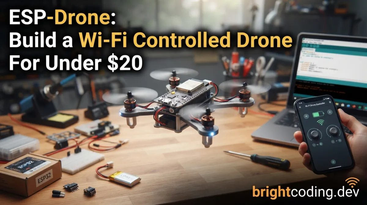
ESP-Drone: Build a Wi-Fi Controlled Drone for Under $20
Stop overpaying for commercial drones you can't hack. What if I told you that the same microcontroller running your smart home projects could power a fully functional, Wi-Fi-controlled quadcopter? Not a toy. Not a gimmick. A real drone development platform that you build, program, and own completely.
The drone industry guards its secrets like classified military tech. Proprietary flight controllers locked behind NDAs. Closed-source firmware you can't audit. Price tags that make hobbyists weep. But somewhere between the $50 toy drones and the $2,000 professional rigs, there's a massive gap that nobody talks about—a space where ESP-Drone thrives.
This isn't just another Arduino toy project. This is a legitimate flight control platform built on the ESP32 that evolved into something far more powerful: the LiteWing drone development ecosystem. Height hold. Position hold. Real-time Wi-Fi control from your smartphone. All running on hardware that costs less than a dinner out.
Ready to unlock the secrets that drone manufacturers don't want you to know? Let's dive deep into the ESP-Drone project and see why thousands of developers are abandoning expensive flight controllers for this open-source revolution.
What is ESP-Drone?
ESP-Drone is an open-source drone development platform created by Circuit Digest, one of the most respected electronics education communities online. Born from a simple DIY tutorial, it has evolved into a sophisticated flight control system that proves the ESP32—a $5 microcontroller—can handle real-time flight stabilization, sensor fusion, and wireless communication simultaneously.
The project's origin story is what makes it special. It didn't start as a commercial product or a research grant. It started as a genuine question: "Can we build a functional drone using only the components hobbyists already have?" The answer was a resounding yes, and that yes grew into something much bigger.
The original ESP-Drone focused on core flight fundamentals: basic stabilization using the MPU6050 IMU (Inertial Measurement Unit) and Wi-Fi-based control through the ESP32's built-in wireless capabilities. But here's where it gets interesting—the firmware architecture was designed with expansion in mind from day one.
As the community grew and demands increased, the project naturally evolved into LiteWing, a more structured development platform that extends the original capabilities dramatically. Today, LiteWing supports advanced features that were once exclusive to expensive commercial flight controllers:
- Altitude Hold: Automatic height maintenance using barometric pressure sensors
- Position Hold: GPS-free position locking through optical flow and advanced sensor fusion
- Modular Hardware Architecture: Swappable sensor modules for different applications
- Developer-Friendly Codebase: Clean, documented firmware that's actually readable
What makes ESP-Drone trending right now is the perfect storm of factors: the ESP32's incredible price-to-performance ratio, the explosion of IoT development skills, and a growing frustration with black-box drone systems. Developers want to understand how their drones work, not just fly them.
Key Features That Make ESP-Drone Insane
Let's cut through the hype and examine what technically makes this platform special. These aren't marketing bullet points—they're architectural decisions that solve real engineering problems.
Dual-Core Real-Time Processing
The ESP32's Xtensa LX6 dual-core processor runs at 240 MHz, and the ESP-Drone firmware exploits this intelligently. One core handles time-critical flight control loops—reading the MPU6050 at hundreds of Hz, running PID controllers, and outputting motor signals with microsecond precision. The other core manages Wi-Fi stack, communication protocols, and user interface updates. This separation prevents network latency from ever destabilizing your flight.
Wi-Fi-Based Control Architecture
Unlike traditional RC drones using dedicated 2.4GHz radio modules, ESP-Drone leverages the ESP32's integrated 802.11 b/g/n Wi-Fi. This eliminates a separate radio chip, reduces cost, and opens fascinating possibilities: control via smartphone apps, web interfaces, or even MQTT integration with home automation systems. The trade-off? Slightly higher latency than dedicated RC protocols—but for development, educational, and indoor applications, it's more than sufficient.
MPU6050 Sensor Fusion
The MPU6050 combines a 3-axis gyroscope and 3-axis accelerometer in a single $2 package. ESP-Drone implements complementary filtering (and in LiteWing, extended Kalman filtering) to fuse these readings into reliable attitude estimation. Pitch, roll, and yaw angles are computed in real-time, enabling self-leveling flight modes that would cost hundreds in commercial equivalents.
Modular Firmware Design
The codebase separates hardware abstraction, flight control algorithms, and communication protocols into distinct layers. Want to swap the MPU6050 for a more advanced MPU9250 with magnetometer? The HAL (Hardware Abstraction Layer) makes it straightforward. Need to add a new flight mode? The control system is modular. This architecture is why the project could evolve from basic stabilization to altitude and position hold without a complete rewrite.
OTA Firmware Updates
Because it's Wi-Fi connected, ESP-Drone supports Over-The-Air firmware updates. No USB cable disassembly when iterating on flight code. Push new PID values, test new features, or deploy bug fixes wirelessly. For development workflows, this is transformative.
Real-World Use Cases Where ESP-Drone Dominates
Theory is cheap. Where does this platform actually deliver value? Here are four concrete scenarios where ESP-Drone isn't just viable—it's optimal.
1. Robotics & Embedded Systems Education
Universities and bootcamps struggle with drone education because commercial platforms are either too simple (toys with no access) or too expensive (crash a $1,500 DJI and explain to accounting). ESP-Drone hits the sweet spot: real flight dynamics, real sensor fusion, real control theory—but with hardware costs under $20 per student. When a crash happens, you replace a $3 propeller, not an entire aircraft. Students can actually modify the PID controllers and see immediate results.
2. Rapid Prototyping for Commercial Drone Startups
Before committing to custom PCB designs and expensive flight controller partnerships, startups need to validate concepts fast. ESP-Drone provides a complete, working flight stack that proves your mechanical design, estimates power consumption, and tests payload integration. The Wi-Fi control means your mobile app team can develop in parallel with hardware. Once validated, migrate to LiteWing's expanded ecosystem or use learnings to design custom hardware.
3. Indoor Inspection & Swarm Robotics Research
GPS-denied environments are where ESP-Drone's evolution into LiteWing shines. The Positioning Module enables optical flow-based position hold without GPS—perfect for warehouses, tunnels, and indoor infrastructure inspection. Multiple units can operate on the same Wi-Fi network, enabling swarm experiments that would be impossible with proprietary RC protocols. Researchers publish papers on algorithms; ESP-Drone provides the hardware platform to test them.
4. Custom IoT-Integrated Applications
Because the drone is an ESP32, integration with existing IoT infrastructure is trivial. Imagine a security drone that publishes telemetry to your Home Assistant instance via MQTT. Or an agricultural monitoring drone that uploads sensor data directly to your cloud backend through its existing Wi-Fi connection. The boundary between "drone" and "flying IoT device" dissolves completely.
Step-by-Step Installation & Setup Guide
Enough theory. Let's build this thing. Here's the complete process from zero to first flight.
Hardware Requirements
| Component | Purpose | Approximate Cost |
|---|---|---|
| ESP32 DevKit V1 | Main flight controller | $4-6 |
| MPU6050 IMU | Attitude sensing | $1-2 |
| 4x Coreless Motors (7x16mm or 8x20mm) | Propulsion | $3-5 |
| 4x Propellers (45mm or 55mm) | Thrust generation | $1 |
| 2x 2N2222 or MOSFETs | Motor driver stage | $1 |
| LiPo Battery (3.7V, 300-500mAh) | Power source | $3-5 |
| Prototype PCB or Breadboard | Assembly | $2 |
| Jumper Wires | Connections | $1 |
| Total | $15-22 |
Wiring Configuration
Connect components as follows:
- MPU6050 VCC → ESP32 3.3V
- MPU6050 GND → ESP32 GND
- MPU6050 SCL → ESP32 GPIO22 (I2C Clock)
- MPU6050 SDA → ESP32 GPIO21 (I2C Data)
- Motor 1 → GPIO25 (Front-Left, CW rotation)
- Motor 2 → GPIO26 (Front-Right, CCW rotation)
- Motor 3 → GPIO27 (Rear-Right, CW rotation)
- Motor 4 → GPIO14 (Rear-Left, CCW rotation)
Note: Motor driver circuitry (transistors/MOSFETs with flyback diodes) required between ESP32 GPIOs and coreless motors. The ESP32 cannot drive motors directly.
Firmware Installation Methods
Method 1: Pre-Compiled Binaries (Fastest)
For immediate testing, use the ESP32 Flash Download Tool with these exact file offsets from the repository:
0x1000    bootloader.bin
0x8000    partition-table.bin
0x10000   ESPDrone.bin
Download the tool from Espressif's official site, select your ESP32 COM port, load the three binaries at their respective addresses, and flash. Power cycle after completion.
Method 2: PlatformIO Build (Recommended for Development)
# Clone the repository
git clone https://github.com/Circuit-Digest/ESP-Drone.git
cd ESP-Drone

# Install PlatformIO (if not already installed)
pip install platformio

# Build the project
pio run

# Upload to connected ESP32
pio run --target upload

# Monitor serial output for debugging
pio device monitor --baud 115200
Method 3: Arduino IDE (Familiar for Beginners)
# Add ESP32 board support in Arduino IDE:
# File → Preferences → Additional Board Manager URLs:
# https://dl.espressif.com/dl/package_esp32_index.json

# Install "ESP32 by Espressif Systems" in Board Manager

# Select: Tools → Board → ESP32 Dev Module
# Select correct COM port and upload
Wi-Fi Configuration & Control App
After flashing, the ESP32 creates an access point:
- SSID:
ESP-Drone(or similar, check serial output) - Password: Typically
12345678or as configured in source
Connect your smartphone to this network, then use any TCP/UDP terminal app or the dedicated control application referenced in the full tutorial. The communication protocol uses simple command packets for throttle, pitch, roll, and yaw values.
REAL Code Examples from the Repository
Let's examine actual implementation patterns from the ESP-Drone project. These aren't simplified tutorials—these are the real architectural decisions that make flight possible.
Example 1: MPU6050 Initialization and Calibration
The IMU setup establishes communication and prepares sensor fusion. Here's the core initialization pattern:
#include <Wire.h>
#include <MPU6050.h>

MPU6050 mpu;  // Create IMU object

// Calibration offsets determined experimentally
int16_t ax_offset = 0, ay_offset = 0, az_offset = 0;
int16_t gx_offset = 0, gy_offset = 0, gz_offset = 0;

void setupMPU6050() {
  Wire.begin(21, 22);  // Initialize I2C with SDA=GPIO21, SCL=GPIO22
  mpu.initialize();     // Wake up the sensor

  // Verify communication - critical for debugging hardware issues
  if (!mpu.testConnection()) {
    Serial.println("MPU6050 connection failed! Check wiring.");
    while (1);  // Halt if sensor not found - prevents dangerous flight
  }

  // Perform calibration by averaging readings at rest
  calibrateMPU6050();

  // Configure digital low-pass filter for noise reduction
  // DLPF_CFG = 3 gives ~42Hz bandwidth, reducing vibration noise
  mpu.setDLPFMode(3);

  // Set gyroscope range to ±250°/s for maximum resolution
  mpu.setFullScaleGyroRange(MPU6050_GYRO_FS_250);

  // Set accelerometer range to ±2g for maximum resolution
  mpu.setFullScaleAccelRange(MPU6050_ACCEL_FS_2);
}

void calibrateMPU6050() {
  // Accumulate 1000 samples while drone is stationary
  long ax_sum = 0, ay_sum = 0, az_sum = 0;
  long gx_sum = 0, gy_sum = 0, gz_sum = 0;

  for (int i = 0; i < 1000; i++) {
    int16_t ax, ay, az, gx, gy, gz;
    mpu.getMotion6(&ax, &ay, &az, &gx, &gy, &gz);
    ax_sum += ax; ay_sum += ay; az_sum += az;
    gx_sum += gx; gy_sum += gy; gz_sum += gz;
    delay(3);  // ~300Hz sample rate during calibration
  }

  // Compute average offsets - subtract these from all future readings
  ax_offset = ax_sum / 1000;
  ay_offset = ay_sum / 1000;
  az_offset = (az_sum / 1000) - 16384;  // Subtract 1g from Z-axis
  gx_offset = gx_sum / 1000;
  gy_offset = gy_sum / 1000;
  gz_offset = gz_sum / 1000;
}
Critical insight: The calibration routine assumes the drone is perfectly level and stationary. The az_offset calculation subtracts 16384 (1g in raw units at ±2g range) because gravity always acts on the Z-axis. This simple subtraction is the foundation of all subsequent attitude estimation—get this wrong, and your "level" reference is permanently tilted.
Example 2: Complementary Filter for Attitude Estimation
Raw sensor data is noisy and incomplete. Accelerometers measure gravity accurately long-term but are corrupted by vibration short-term. Gyroscopes are smooth short-term but drift over minutes. The complementary filter fuses both:
// Attitude angles in degrees
float pitch = 0.0, roll = 0.0, yaw = 0.0;

// Filter coefficient: 0.98 gyro, 0.02 accel (tune for your vibration environment)
const float alpha = 0.98;
const float dt = 0.004;  // 250Hz update rate = 4ms period

void updateAttitude() {
  int16_t ax, ay, az, gx, gy, gz;
  mpu.getMotion6(&ax, &ay, &az, &gx, &gy, &gz);

  // Apply calibration offsets
  ax -= ax_offset; ay -= ay_offset; az -= az_offset;
  gx -= gx_offset; gy -= gy_offset; gz -= gz_offset;

  // Convert gyro readings to degrees/second
  // At ±250°/s range: 131 LSB/(°/s)
  float gyroX = gx / 131.0;
  float gyroY = gy / 131.0;
  float gyroZ = gz / 131.0;

  // Calculate accelerometer angles (noisy but absolute reference)
  // atan2(y, z) gives pitch; atan2(-x, z) gives roll
  float accelPitch = atan2(ay, sqrt(ax*ax + az*az)) * 180.0 / PI;
  float accelRoll = atan2(-ax, sqrt(ay*ay + az*az)) * 180.0 / PI;

  // Complementary filter: trust gyro for fast changes, accel for slow drift correction
  pitch = alpha * (pitch + gyroX * dt) + (1 - alpha) * accelPitch;
  roll  = alpha * (roll  + gyroY * dt) + (1 - alpha) * accelRoll;

  // Yaw has no accelerometer reference (gravity doesn't help), so pure integration
  yaw += gyroZ * dt;

  // Normalize yaw to ±180 degrees to prevent floating-point growth
  if (yaw > 180) yaw -= 360;
  if (yaw < -180) yaw += 360;
}
Why this matters: The alpha = 0.98 value is your tuning knob. More vibration? Increase alpha to trust gyro more. More gyro drift? Decrease alpha to correct faster from accelerometer. This single parameter separates stable flight from oscillating instability. The 250Hz update rate (4ms) is near the practical limit of I2C communication with the MPU6050—any faster and you spend all your time waiting for bus transactions.
Example 3: PID Motor Control Loop
The final output: converting desired attitude to motor power. This is the flight controller's heartbeat:
// PID gains - THESE REQUIRE TUNING FOR YOUR SPECIFIC BUILD
float Kp_roll = 1.2, Ki_roll = 0.0, Kd_roll = 0.15;
float Kp_pitch = 1.2, Ki_pitch = 0.0, Kd_pitch = 0.15;
float Kp_yaw = 2.0, Ki_yaw = 0.0, Kd_yaw = 0.0;

// PID state variables
float roll_error_prev = 0, pitch_error_prev = 0, yaw_error_prev = 0;
float roll_integral = 0, pitch_integral = 0, yaw_integral = 0;

// Motor outputs: 1000-2000 microsecond PWM typical for ESCs
// Coreless direct-drive uses simpler PWM 0-255
uint16_t motorFL, motorFR, motorRL, motorRR;

void updateMotors(float throttle, float target_roll, float target_pitch, float target_yaw) {
  // Calculate errors: where we want to be minus where we are
  float roll_error = target_roll - roll;
  float pitch_error = target_pitch - pitch;
  float yaw_error = target_yaw - yaw;

  // Proportional term: immediate response to error
  float roll_P = Kp_roll * roll_error;
  float pitch_P = Kp_pitch * pitch_error;
  float yaw_P = Kp_yaw * yaw_error;

  // Integral term: accumulate error over time (disabled here with Ki=0)
  roll_integral += roll_error * dt;
  pitch_integral += pitch_error * dt;
  yaw_integral += yaw_error * dt;

  // Anti-windup: clamp integral to prevent runaway
  roll_integral = constrain(roll_integral, -100, 100);
  pitch_integral = constrain(pitch_integral, -100, 100);
  yaw_integral = constrain(yaw_integral, -100, 100);

  float roll_I = Ki_roll * roll_integral;
  float pitch_I = Ki_pitch * pitch_integral;
  float yaw_I = Ki_yaw * yaw_integral;

  // Derivative term: rate of error change (dampens oscillation)
  float roll_D = Kd_roll * (roll_error - roll_error_prev) / dt;
  float pitch_D = Kd_pitch * (pitch_error - pitch_error_prev) / dt;
  float yaw_D = Kd_yaw * (yaw_error - yaw_error_prev) / dt;

  roll_error_prev = roll_error;
  pitch_error_prev = pitch_error;
  yaw_error_prev = yaw_error;

  // Combine PID terms
  float roll_output = roll_P + roll_I + roll_D;
  float pitch_output = pitch_P + pitch_I + pitch_D;
  float yaw_output = yaw_P + yaw_I + yaw_D;

  // Mix to motor outputs: X-configuration quadcopter
  // Front-Left:  throttle + pitch + roll - yaw
  // Front-Right: throttle + pitch - roll + yaw
  // Rear-Left:   throttle - pitch + roll + yaw
  // Rear-Right:  throttle - pitch - roll - yaw
  motorFL = throttle + pitch_output + roll_output - yaw_output;
  motorFR = throttle + pitch_output - roll_output + yaw_output;
  motorRL = throttle - pitch_output + roll_output + yaw_output;
  motorRR = throttle - pitch_output - roll_output - yaw_output;

  // Constrain to valid PWM range and prevent motor stop during flight
  motorFL = constrain(motorFL, 1000, 2000);
  motorFR = constrain(motorFR, 1000, 2000);
  motorRL = constrain(motorRL, 1000, 2000);
  motorRR = constrain(motorRR, 1000, 2000);

  // Output to GPIO pins (simplified - actual implementation uses LEDC PWM)
  ledcWrite(MOTOR_FL_CHANNEL, motorFL);
  ledcWrite(MOTOR_FR_CHANNEL, motorFR);
  ledcWrite(MOTOR_RL_CHANNEL, motorRL);
  ledcWrite(MOTOR_RR_CHANNEL, motorRR);
}
The mixing math reveals why quadcopters work: Each motor contributes to multiple axes simultaneously. To pitch forward, you increase rear motors and decrease front motors—but this also changes total thrust. The mixing equations automatically compensate: the +pitch_output and -pitch_output terms cancel for total thrust while creating the desired torque. Pure elegance.
Advanced Usage & Best Practices
PID Tuning Without Crashing
Start with rate mode (no self-leveling) to tune P-gains. Increase until oscillation, then back off 20%. Add D-term to dampen. Integral is often unnecessary for small drones—save it for fighting wind in outdoor builds.
Vibration Isolation is Everything
The MPU6050 must be soft-mounted. Hard-mounted on frame = vibration aliasing into attitude estimate = impossible to tune. Use double-sided foam tape, gel pads, or 3D-printed TPU mounts.
Power Supply Sanity
Voltage sag during throttle punches causes brownouts and ESP32 resets. Use capacitors (1000µF+ low-ESR) across battery terminals, and monitor voltage in firmware. Implement gradual throttle limiting below 3.3V/cell.
Wi-Fi Range Optimization
The ESP32's PCB antenna is weak for drone use. For serious range, use external antenna variants (ESP32-WROOM-32U with U.FL connector). Reduce Wi-Fi TX power when close to minimize interference and current draw.
Comparison with Alternatives
| Feature | ESP-Drone | Betaflight (F4/F7) | DJI Naza | Arduino Uno + NRF24 |
|---|---|---|---|---|
| Cost | ~$15 | ~$50-150 | ~$200+ | ~$25 |
| Open Source | ✅ Full | ✅ Firmware only | ❌ No | ✅ Full |
| Wi-Fi Built-in | ✅ Yes | ❌ No | ❌ No | ❌ No |
| Self-Leveling | ✅ Yes | ✅ Yes | ✅ Yes | ⚠️ Basic |
| Position Hold | ✅ LiteWing | ⚠️ GPS required | ✅ GPS | ❌ No |
| Code Accessibility | ✅ Excellent | ⚠️ Complex | ❌ None | ✅ Good |
| Community | Growing | Massive | Commercial | Hobby |
| Best For | Learning/IoT | Racing/Acro | Cinematography | Simple toys |
Choose ESP-Drone when: You want to understand flight control, integrate with IoT, minimize cost, or need GPS-denied navigation. Choose Betaflight when: You need maximum performance for FPV racing with mature tuning tools. Choose DJI when: Budget is unlimited and you need cinematic reliability without code access.
Frequently Asked Questions
Is ESP-Drone stable enough for aerial photography?
For lightweight cameras (under 50g), yes—with LiteWing's position hold and careful PID tuning. For professional gimbals, you'll need more powerful motors and potentially migrate to a heavier platform. Start with FPV micro cameras.
Can I add GPS for outdoor waypoint missions?
LiteWing's modular architecture supports GPS modules via UART. The ESP32 has three UARTs available—one for debugging, one for GPS, and potential expansion. Implementing full waypoint navigation requires significant firmware development beyond the base project.
What's the actual Wi-Fi control range?
With PCB antenna: 30-50 meters line-of-sight. With external antenna: 100+ meters. For beyond-visual-line-of-sight, you'd need to implement ESP-NOW protocol or add traditional RC as backup—both possible with the hardware.
How does it compare to ESP-Drone projects using ESP8266?
The ESP8266 lacks the dual-core processing and hardware FPU of ESP32. Single-core means flight control interrupts Wi-Fi, causing latency spikes. ESP32's dedicated core separation is architecturally superior for real-time control.
Is the smartphone app source code available?
The base project focuses on firmware. Community members have built control apps using MIT App Inventor, Flutter, and React↗ Bright Coding Blog Native. The communication protocol is simple enough to reverse-engineer from the firmware's Wi-Fi packet handling.
Can I use brushless motors instead of coreless?
Yes, but this requires ESC (Electronic Speed Controller) integration instead of direct transistor drive. The PWM output logic remains identical—just connect to ESC signal inputs instead. ESCs require 5V logic, so level shifting from ESP32's 3.3V may be needed.
What's the path from ESP-Drone to LiteWing?
LiteWing is the commercialized evolution with professional support, additional sensor modules, and structured documentation. Start with ESP-Drone to learn fundamentals, then migrate to LiteWing when you need altitude hold, optical flow positioning, or commercial deployment.
Conclusion: Your $15 Ticket to Flight Control Mastery
The drone industry wants you to believe that flight control is black magic requiring proprietary silicon and NDAs. ESP-Drone exposes that lie. With nothing more than a $5 ESP32, a $2 IMU, and open-source code, you can build a self-stabilizing quadcopter that responds to your smartphone over Wi-Fi.
The real value isn't the hardware—it's the understanding you gain. PID controllers that were abstract textbook concepts become tangible knobs you tune. Sensor fusion theory becomes visible in your serial plotter. The boundary between "embedded developer" and "drone engineer" dissolves.
And when you're ready for more? The evolution to LiteWing provides altitude hold, position lock, and modular expansion—proving this wasn't a toy project, but a genuine development platform architecture.
Stop buying drones. Start building them. Fork the repository, order the parts, and join the community of developers who refuse to accept that flight control should be a black box.
👉 Get the complete ESP-Drone source code on GitHub
👉 Explore the LiteWing platform and advanced modules
👉 Watch the build video: How to Build an ESP32 Drone
The sky isn't the limit—it's just the beginning.
Explore on the BrightCoding network
Hand-picked resources from our other sites.
Serial-Studio/Serial-Studio: Open-Source Telemetry Dashboard for Hardware
Serial-Studio/Serial-Studio is an open-source telemetry dashboard with 7,043 GitHub stars that combines serial monitoring, live visualization, and data logging...
lvgl/lvgl: Embedded UI Library for MCUs, MPUs, and Any Display
lvgl/lvgl is a portable, MIT-licensed C graphics library for building UIs on any MCU or MPU. Zero dependencies, 24K+ stars, 30+ widgets, and support for display...
reBot-DevArm: The Open Source Robot Arm Top AI Labs Are Secretly Using
Discover reBot-DevArm, the 100% open source robotic arm with full hardware blueprints (CERN-OHL-W-2.0) and software stack (Apache-2.0). Features ROS2, LeRobot,...
Continuez votre lecture
Stop Locking Yourself Into Vendor Firmware! Use OpenWrt Instead
Stop Wasting Money on IoT Modules! TTGO-LoRa32-V2.1 Does It All
Stop Wrestling with Vendor Firmware! Use Lienol/openwrt Instead

Stop Coding Alone: OPC-Skills Gives Your AI Agent Superpowers
Commentaires 0
Aucun commentaire pour l'instant. Soyez le premier à réagir !